What is the Testbench? FPGA Simulation, TCL – Tool Command Language
Before reading this article, you should read the article about HDLs: (LINK HERE )
The Github folder for this article: (LINK HERE)
1./ What is the Testbench:
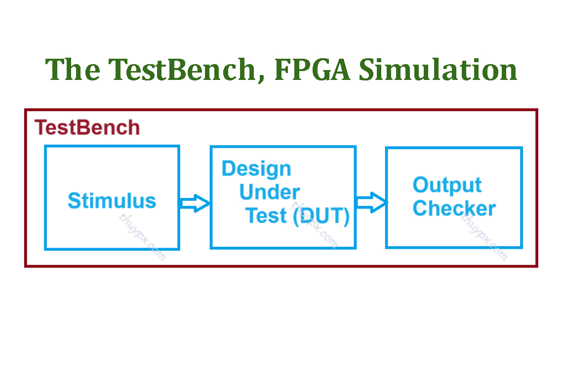
+ One of the main uses of an HDL is that of simulating a new design to ensure that the design is correct. To simulate a design, we need to set the design’s inputs to certain values, and then check that the design’s output values are what we expect them to be. A system that sets input values and checks output values is known as a testbench.
+ Creating test benches for your FPGA design is a critical step for any FPGA design project. The VHDL, Verilog test benches are used for the simulation and verification of FPGA designs.

+ The Testbench does not contain any external ports, just internal signals that connect the two instantiated components. Testbench automatically generates inputs and checks the output with the provided inputs.
+ FPGA Software provides HDL Simulators, you can look up information here: List of HDL Simulators.
2./ TestBench Structure
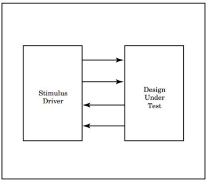
The testbench has two main components:
- The first being the Design Under Test (DUT) or the Unit Under Test (UUT), the Design Under Verification (DUV).
- The second the stimulus driver.

A testbench is used to verify the functionality of a design.
A testbench is at the highest level in the hierarchy of the design (The top-level design). The testbench instantiates the design under test (DUT). The testbench provides the necessary input stimulus to the DUT and examines the output from the DUT.

=> The stimulus driver drives inputs into the DUT.
There are two ways to create input stimulus:
- Using an interactive waveform editor (easy).
- Using a testbench (a bit harder).
=> The DUT responds to the input signals and produces output results.
=> Finally, a compare function within the testbench compares the results from the DUT against those known good results and reports any discrepancies.
3./ Programming language for TestBench
Let’s learn about Programming languages for TestBench through examples.
We will learn how to write TestBench for programs with AND Gate, so you can grasp the problem as quickly as possible. If you start learning about TestBench for complex designs, it will be harder for you to approach and understand the problem.
3.1./ VHDL testbench
=> Attention: VHDL code of AND gate, you read in this link about HDLs.
We will write a VHDL testbench for this AND gate.
3.1.1./ Write VHDL testbench and run on Quartus, ModelSim
- -- Vhdl Test Bench template for design : ANDGATE
- --
- -- Simulation tool : ModelSim-Altera (VHDL)
- --
- LIBRARY ieee;
- USE ieee.std_logic_1164.all;
- ENTITY ANDGATE_vhd_tst IS
- END ANDGATE_vhd_tst;
- ARCHITECTURE ANDGATE_arch OF ANDGATE_vhd_tst IS
- -- constants
- -- signals
- SIGNAL I1 : STD_LOGIC;
- SIGNAL I2 : STD_LOGIC;
- SIGNAL O : STD_LOGIC;
- COMPONENT ANDGATE
- PORT (
- I1 : IN STD_LOGIC;
- I2 : IN STD_LOGIC;
- O : OUT STD_LOGIC
- );
- END COMPONENT;
- BEGIN
- dut : ANDGATE
- PORT MAP (
- -- list connections between master ports and signals
- I1 => I1,
- I2 => I2,
- O => O
- );
- init : PROCESS
- -- variable declarations
- BEGIN
- -- code that executes only once
- I1 <= '0';
- I2 <= '0';
- wait for 1 ps;
- I1 <= '0';
- I2 <= '1';
- wait for 1 ps;
- I1 <= '1';
- I2 <= '0';
- wait for 1 ps;
- I1 <= '1';
- I2 <= '1';
- wait for 1 ps;
- WAIT;
- END PROCESS init;
- always : PROCESS
- -- optional sensitivity list
- -- ( )
- -- variable declarations
- BEGIN
- -- code executes for every event on sensitivity list
- WAIT;
- END PROCESS always;
- END ANDGATE_arch;
3.1.2./ Write VHDL testbench and run on Vivado
- library IEEE;
- use IEEE.std_logic_1164.all;
- use std.env.finish;
- -- creat VHDL testbench entity has no input or output
- entity and_vhdl_tb is
- end entity and_vhdl_tb;
- -- describe the architecture of VHDL testbench entity
- architecture behave of and_vhdl_tb is
- signal r_I1: std_logic;
- signal r_I2: std_logic;
- signal w_O: std_logic;
- begin
- -- instantiate the uut, using and_vhdl entity in and_vhdl_tb architecture
- -- the Working Library: contains the compiled version of your design. The contents of a working library change every time you compile your design.
- -- the default working library is named "work"
- uut : entity work.and_vhdl
- port map(
- I1 => r_I1,
- I2 => r_I2,
- O => w_O
- );
- -- start at the begining of the simulation
- process is
- begin
- r_I1 <= '0';
- r_I2 <= '0';
- wait for 5ps;
- r_I1 <= '0';
- r_I2 <= '1';
- wait for 5ps;
- r_I1 <= '1';
- r_I2 <= '0';
- wait for 5ps;
- r_I1 <= '1';
- r_I2 <= '1';
- wait for 5ps;
- --finish;
- wait;
- end process;
- end behave;
3.2./ Verilog testbench
=> Attention: Verilog code of AND gate, you read in this link about HDLs.
We will write a Verilog testbench for this AND gate.
3.2.1./ Write Verilog testbench and run on Quartus, ModelSim
- // Verilog Test Bench template for design : and_verrilog
- //
- // Simulation tool : ModelSim-Altera (Verilog)
- //
- `timescale 1 ps/ 1 ps
- module and_verrilog_vlg_tst();
- // constants
- // general purpose registers
- reg eachvec;
- // test vector input registers
- reg a;
- reg b;
- // wires
- wire c;
- // assign statements (if any)
- and_verrilog i1 (
- // port map - connection between master ports and signals/registers
- .a(a),
- .b(b),
- .c(c)
- );
- initial
- begin
- // code that executes only once
- // insert code here --> begin
- a = 0;
- b = 0;
- // --> end
- $display("Running testbench");
- end
- always
- // optional sensitivity list
- // @(event1 or event2 or .... eventn)
- begin
- // code executes for every event on sensitivity list
- // insert code here --> begin
- $dumpfile("and_verilog_test.vcd"); $dumpvars;
- $monitor("Time= %3d : a= %d,b= %d, c=%d \n",$time,a,b,c);
- a <= 1'b0;
- b <= 1'b0;
- #5;
- $monitor("Time= %3d : a= %d,b= %d, c=%d \n",$time,a,b,c);
- a <= 1'b0;
- b <= 1'b1;
- #5;
- $monitor("Time= %3d : a= %d,b= %d, c=%d \n",$time,a,b,c);
- a <= 1'b1;
- b <= 1'b0;
- #5;
- $monitor("Time= %3d : a= %d,b= %d, c=%d \n",$time,a,b,c);
- a <= 1'b1;
- b <= 1'b1;
- #5;
- $display("Finish testbench");
- @eachvec;
- // --> end
- end
- endmodule
3.2.2./ Write Verilog testbench and run on Vivado
- // Verilog Test Bench template for design : and_verrilog
- //
- // Simulation tool : Xilinx Vivado (Verilog)
- //
- `timescale 1 ps/ 1 ps
- module and_verrilog_vlg_tst();
- // test vector input registers
- reg a;
- reg b;
- // wires
- wire c;
- // assign statements (if any)
- and_verrilog i1 (
- // port map - connection between master ports and signals/registers
- .a(a),
- .b(b),
- .c(c)
- );
- initial
- begin
- // code that executes only once
- // insert code here --> begin
- a = 0;
- b = 0;
- // --> end
- $display("Running testbench");
- end
- always
- // optional sensitivity list
- // @(event1 or event2 or .... eventn)
- begin
- // code executes for every event on sensitivity list
- // insert code here --> begin
- $dumpfile("and_verilog_test.vcd"); $dumpvars;
- $monitor("Time= %3d : a= %d,b= %d, c=%d \n",$time,a,b,c);
- a <= 1'b0;
- b <= 1'b0;
- #5;
- $monitor("Time= %3d : a= %d,b= %d, c=%d \n",$time,a,b,c);
- a <= 1'b0;
- b <= 1'b1;
- #5;
- $monitor("Time= %3d : a= %d,b= %d, c=%d \n",$time,a,b,c);
- a <= 1'b1;
- b <= 1'b0;
- #5;
- $monitor("Time= %3d : a= %d,b= %d, c=%d \n",$time,a,b,c);
- a <= 1'b1;
- b <= 1'b1;
- #5;
- $display("Finish testbench");
- // --> end
- end
- endmodule
Có thể bạn cũng thích

What is Look-Up Tables (LUTs) in FPGA (Look-Up Tables, LUT là gì?)
Tháng 7 7, 2024
About XILINX Vivado and How to install XILINX Vivado ML 2022.2 on Ubuntu 22.04
Tháng 5 2, 2025


