HDL – Hardware Description Language, VHDL, Verilog
The Github folder for this article: (LINK HERE)
1./ Introduce about HDL
Hardware Description Language (HDL) is a specialized computer language used to describe the structure, behavior and timing of electronic circuits, digital circuit, most commonly to design ASICs and program FPGAs. HDLs are also used to stimulate the circuit and check its response.
There are many HDL languages, however two popular HDL languages are: Verilog and VHDL. Both VHDL and Verilog are officially endorsed IEEE (Institute of Electrical and Electronics Engineers) standards.
There are also JHDL (Java HDL), Active-HDL of Cypress Semiconductor Corporation,… You can refer to Wiki for more information.
2./ Compare HDL with common programming languages
HDL is similar to other programming languages, it is a textual description consisting of expressions, statements and control structures. However, it has big differences compared to other programming languages such as: C/C++/Python, …
+ They are specialized for describing hardware, while languages such as C/C++/Python, etc. are used for software development as applications.
+ Most programming languages are inherently procedural (single-threaded), with limited syntactical and semantic support to handle concurrency. HDLs, on the other hand, resemble concurrent programming languages in their ability to model multiple parallel processes (such as flip-flops and adders) that automatically execute independently of one another. (Ref Wiki)
3./ Introducing VHDL and VHDL program structure
VHDL (VHSIC Hardware Description Language) is a hardware description programming language used for VHSIC (Very High Speed Integrated Circuits) high-speed integrated circuits. The first version of VHDL was born in 1983, a combined product of three large companies, IBM, Texas Instruments, and Intermetric under contract with the US Department of Defense.
After its birth, in 1987, VHDL was accepted by IEEE as one of their standards and called the IEEE 1076 standard. VHDL is always revised and upgraded with different versions, the latest version IEEE Std 1076 -2019.
VHDL is designed to fill a number of needs in the design process.
+ Firstly: it allows description of the structure of a design, that is how it is decomposed into sub-designs, and how those sub-designs are interconnnected.
+ Secondly: it allows the specification of the function of designs using familiar programming language forms.
+ Thirdly: as a result, it allows a design to be simulated before being manufactured, so that designers can quickly compare alternatives and test for correctness without the delay and expense of hardware prototyping.
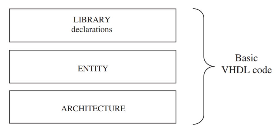
A standalone piece of VHDL code is composed of at least three fundamental sections:
+ LIBRARY declarations: Contains a list of all libraries to be used in the design. For example: ieee, std, work, etc.
+ ENTITY: Specifies the I/O pins of the circuit
+ ARCHITECTURE: Contains the VHDL code proper, which describes how the circuit should behave (function).

-- example VHDL code with AND Gate
-- import std_logic from the IEEE library
library IEEE;
use IEEE.std_logic_1164.all;

-- this is the entity
entity ANDGATE is
  port (
    I1 : in std_logic;
    I2 : in std_logic;
    O  : out std_logic);
end entity ANDGATE;

-- this is the architecture
architecture RTL of ANDGATE is
begin
  O <= I1 and I2;
end architecture RTL;
Creating VHDL Project on Quatus, and VHDL Testbench Simulation on ModelSim.
Creating VHDL Project and VHDL Testbench Simulation on Xilinx Vivado.
4./ Introducing Verilog and Verilog program structure
Verilog was created by Prabhu Goel, Phil Moorby and Chi-Lai Huang between late 1983 and early 1984.
Verilog, standardized as IEEE 1364-1995 (VHDL IEEE 1076-1993), is a hardware description language (HDL) used to model electronic systems. In 2005, SystemVerilog was introduced as an extension of Verilog with object-oriented programming techniques. In 2009, IEEE combined the Verilog and SystemVerilog standards into a single standard: IEEE 1800-2009. The latest version IEEE 1800-2023 (6 December 2023).
It is most commonly used in the design and verification of digital circuits at the register-transfer level (RTL) of abstraction (synthesis and simulation).
In Verilog, circuit components are designed inside a module. Modules can contain both structural and behavioral statements.
- Structural statements represent circuit components like logic gates, counters, and microprocessors.
- Behavioral level statements are programming statements that have no direct mapping to circuit components like loops, ifthen statements, and stimulus vectors which are used to exercise a circuit.
Modules are the fundamental descriptive units in Verilog HDL. Verilog modules, like functions in other programming languages.
Verilog modules are declared using the module keyword, and are ended with the endmodule keyword.
Module Format:
module MyModule ([parameters]);
     inputs ...
     outputs ...
     internal variables ...
     ...
     Module Code ...
endmodule
Example with AND Gate:
// example Verilog code with AND Gate
module AND(a, b, c);
   input a, b;
   output c;
   assign c = a & b;
endmodule
Example with NAND Gate:
// example Verilog code with NAND Gate
// create a NAND gate out of an AND and an Invertor
module NAND(c, a, b);
// declare port signals
output c;
input a, b;
// declare internal wire
wire d;
//instantiate structural logic gates
and a1(d, a, b); //d is output, a and b are inputs
not n1(c, d); //c is output, d is input
endmodule
5./ Summary:
VHDL vs Verilog – Which Language Is Better for FPGA?
+ Two popular HDL languages are: Verilog and VHDL.
+ Choosing Verilog or VHDL for your studies and projects depends on the market needs where you work or live, sometimes it is your preference, maybe you can do both with VHDL and Verilog.
+ Most people evaluate that VHDL is more difficult to learn than Verilog, however, I think you should be confident, if you find a problem difficult, learn calmly, step by step to understand and solve the problem.
Có thể bạn cũng thích

How to Install ModelSim – Intel FPGA Starter Edition on Ubuntu 22.04
Tháng 6 14, 2025
Củ Dền nấu Mía
Tháng 5 19, 2025


